¶ Linear Rails for the X-Axis on the AnkerMake M5
¶ This more than likely voids your warranty for your X-Axis, you have been warned
¶ Required Purchases:
- uniTak3D Ender 3 Pro V2 Linear Rail X-axis conversion kit
- https://amzn.to/3OXwT0z
- UniTak3D MGN12 Linear Guide Rail 350mm with MGN12H Bearing
- https://amzn.to/43mkckb
¶ Required Tools:
- Calipers
- Center Punch or very thin marker to mark holes
- Drill or Drill Press
- M2, M3, and M6 Taps
- M2, M3, and M6 Drill Bits
- M2, M3, and M6 nuts and bolts
NOTE: You can most likely get away with the set of nuts and bolts that are provided in the above required purchases. I had these items on hand and did not require any additional supplies.
¶ Proficiency Skills Required
★★★✩✩ (3/5) Medium
- Need to be proficient in measuring with calipers
- Need to be proficient in drilling straight holes
- Need to be proficient in tapping the drilled holes
- Need to be proficient at dismantling your M5 and not losing nuts, bolts, or screws 😂
WARNING: You will have to take apart the entire hotend and the X-Axis to do this modification
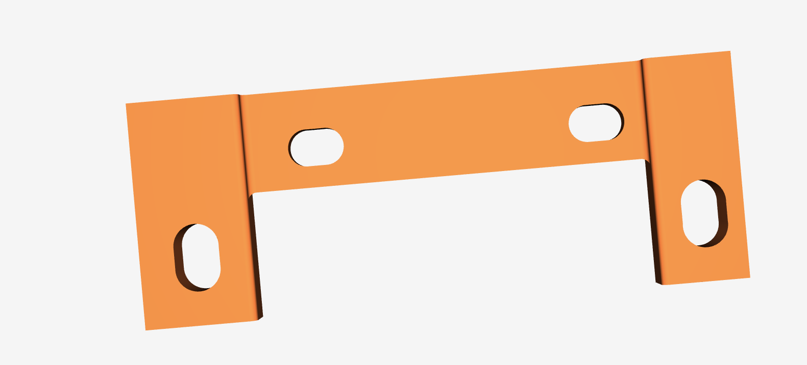
¶ Required Printed Part
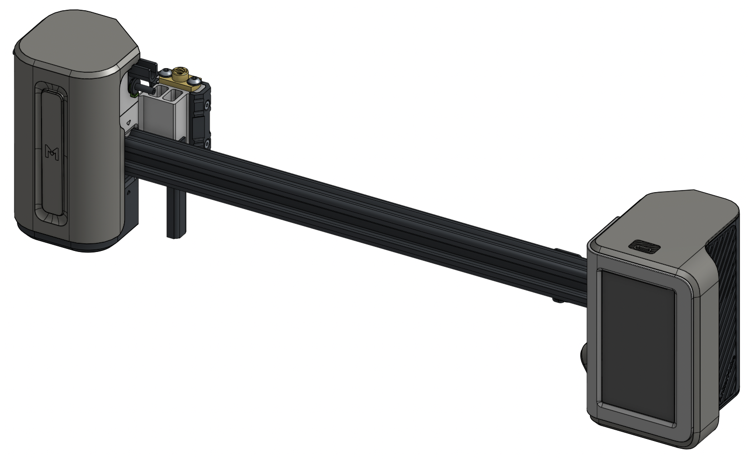
¶ Finished Product
¶ How to:
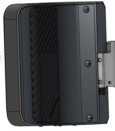
¶ Removing the Hotend
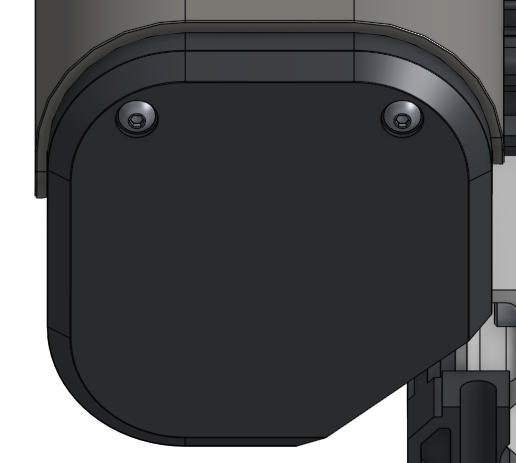
Remove the 2 bolts that hold the USB-C cable to the hotend. Additionally, remove the filament tube.
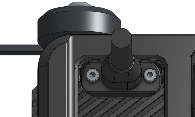
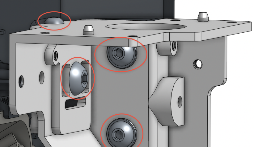
Now from the back of the hotend, there are 4 bolts that need to be removed to start getting the cover off (highlighted in red)
Remove the top lid and cover leaving the green bottom in place (there is another screw we must get to after the cover is removed)
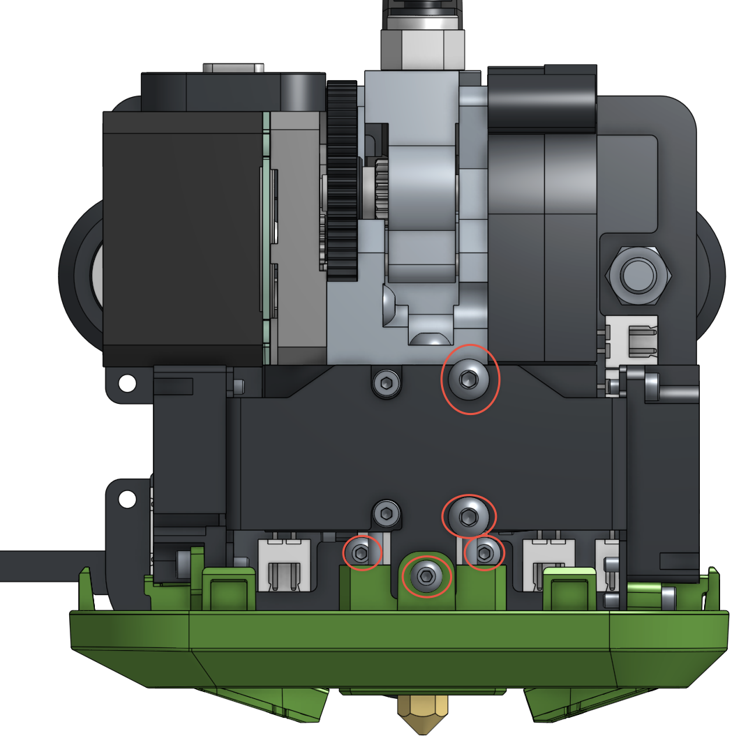
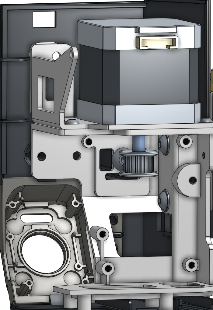
Going to the front, there are five more screws to remove. The one screw in the green bottom will release that piece from the hotend. The two on the fan bracket will release the bracket, be gentle and unplug the fans to remove them. Then the back two screws will loosen the hotend from the backplate
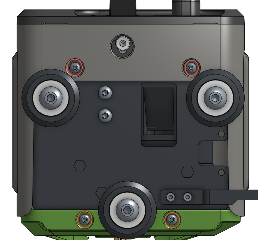
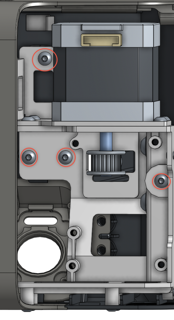
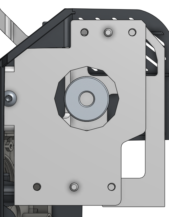
Now we go to the back plate again and remove the screws highlighted in red. Remove the wheel screw last. The three in the plate will remove the entire extruder from the backplate. Finally remove the X-stop as this mod will create a new X-Stop.
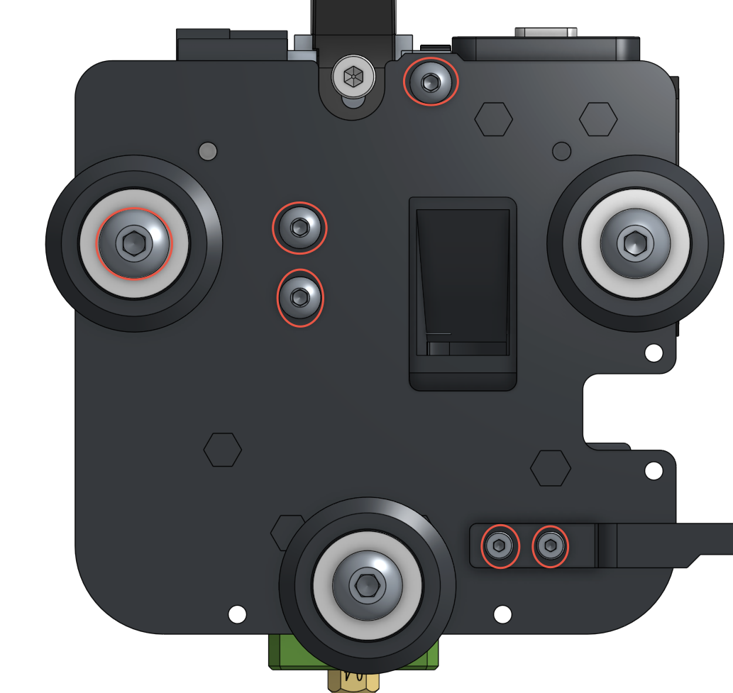
After removing the wheel, you may need to loosen the bottom one to remove the entire plate. At this time you will now have the entire extruder off and ready to dismantle the X-Axis.
¶ Dismantle the X-Axis
¶ Right Tower
Starting with the Right Gantry (the one with the screen)
- Remove the 4 bolts on the bottom of the gantry pod
2. Remove the 3 bolts from the back of the gantry pod
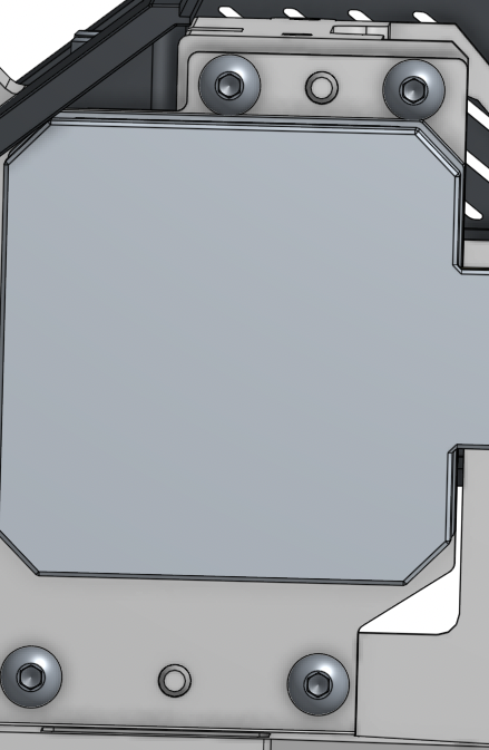
3. Remove the 4 bolts that are highlight with Red circles
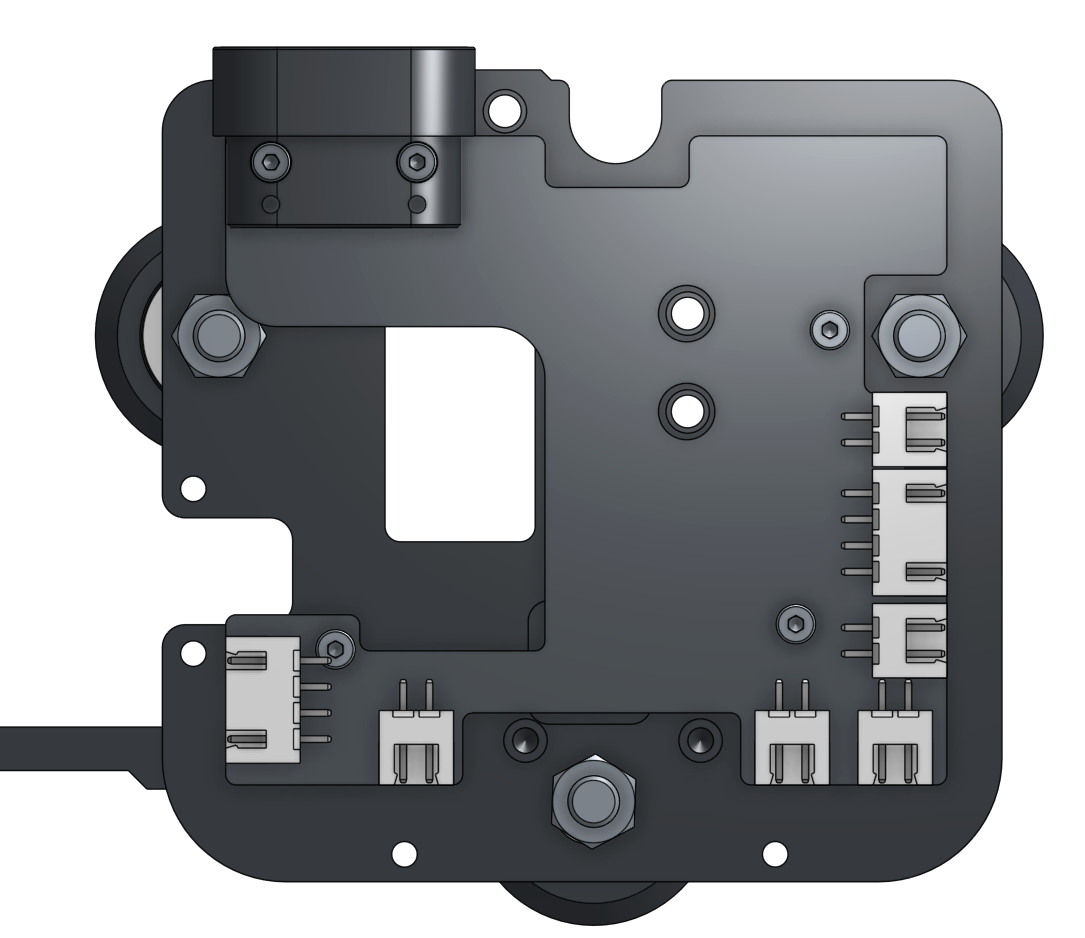
Now this will allow you to remove the rest of the housing. Please disconnect all ribbon cables and power cables from the board that is behind the screen. Your Right Gantry should look like this:
5.Loosen the belt from the left gantry, then remove the 4 screws that hold the motor and remove the motor
 |
 |
Upon removing the motor your gantry should look like the left picture above.
Almost to the end here for the Right Gantry, remove the below bolts highlight in red
Upon completion of the above step, your X-axis gantry will become free from the right side tower.
¶ Left Tower
To remove the cover you need to unbolt 3 bolts
 |
|
Once the cover is off, remove the screws highlighted in the below photo (Editor's Note: The CAD model used did not have these screws modeled but they will be there on your machine)

Now, you should be able to remove the filament sensor and the retaining case that is the top of this gantry.
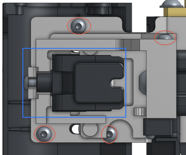
With the belt removed during the “Remove Hotend” steps you will need to loosen the tensioner system to be able to remove it from it's housing. (highlighted in blue)
With the filament sensor and tensioner gone, you will have 4 more bolts to remove:
Upon Completion of this step your entire X-Axis bar will be free for the next steps.
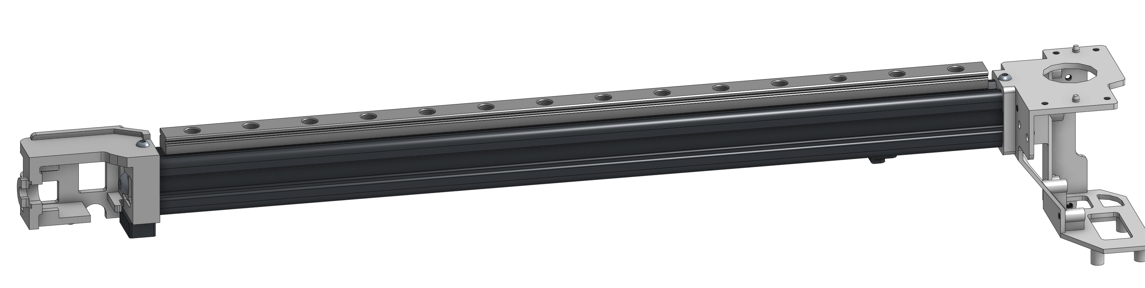
¶ Installation of Linear Rail
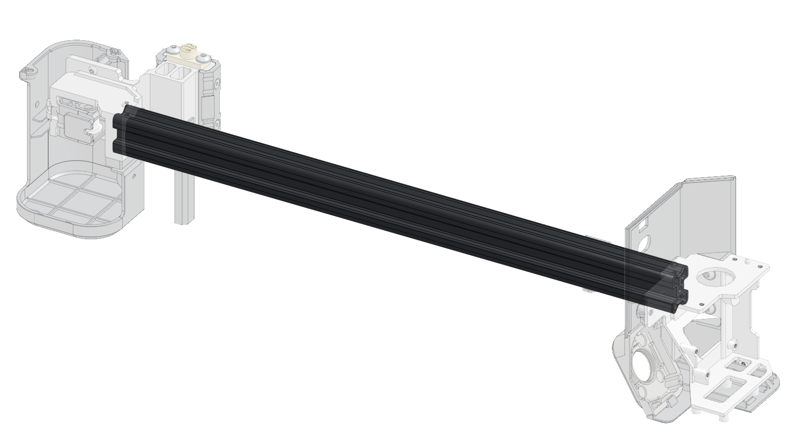
In the above picture please take note of the silver streaks on each end of the rail where the linear rail meets. These are measurements of where the gantry goes inside the tower mounts. The first part of installation of the Linear Rail is to take exact measurements of how deep your rail goes into the towers.
The measurement should be 359 millimeters but due to manufacturer variances please verify on your model. The linear rail is 350mm. You will need to center the linear rail
Once you have centered your linear rail to the X-Axis rail, mark your holes with a center punch. We have tested with just two holes mounting the rail to the X-axis but for securing it permanently you should at least do at least 4-6 holes to ensure no movement of the linear rail.
WARNING: Please check multiple times that your linear rail, X-Axis, and the tower pieces as shown in the above photo ALL fit together before drilling ANY holes. If you mess this stage up, you will not be able to finish.
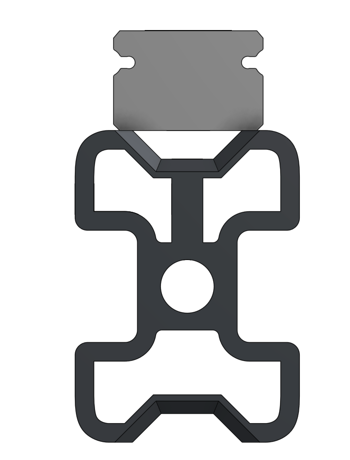
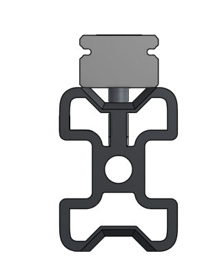
Once marked or punched, drill the holes. You need to be as straight and centered as possible so that you will ensure drilling into the support of the X-Axis. The X-Axis has a bar that runs through the top center that you want to utilize as the place for the screws.
Upon completion of drilling, you will need to clean, then tap the threads into those holes matching the screws. If using the recommended kit, those screws are M3x8mm so you will want to use an M3 tap.
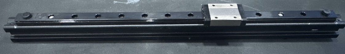
Your X-Axis should look similar to this once completed:
Do not forget to install the linear carriage before putting everything back together.
At this stage, you now just need to follow the instructions in reverse to reinstall everything.
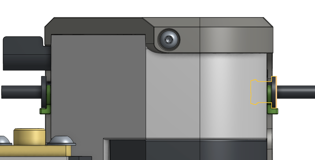
When reinstalling the hotend extruder you will need to print out the coupler and attach it like the following photos:
 |
 |
You will be removing the top two wheels and install a nut and bolt into the bottom holes in the coupler. This attaches the extruder to the coupler. You then screw the coupler into the carriage mount in the top holes and now you are connected to the printer physically. The rest of the steps in this document can now be followed in reverse order to completion.